
What a Bar Magnet Is
A bar magnet is a permanent magnet formed as an elongated piece, usually with a rectangular or cylindrical cross-section. Its length is greater than its width or diameter, giving it the familiar straight, bar-like shape. When magnetized along its length, opposite poles are usually located at the two ends. Magnet Guide is an independent English-language information guide about magnetism and familiar magnet types.
Shape and Basic Structure
The defining feature of a bar magnet is its elongated form: the length is noticeably greater than the width and thickness, or than the diameter in a rod-shaped version. A small educational model might measure a few centimeters long, while larger examples can extend to several tens of centimeters. The cross-section is commonly rectangular, square, or circular; the term describes the overall proportions rather than one exact cross-section.
In a typical bar magnet, magnetization runs along the long axis. The north and south poles of a magnet are then positioned near opposite ends, rather than distributed along the broad faces. The ends may be flat, rounded, or slightly beveled, depending on how the magnet is manufactured. A protective coating or casing can also alter the exterior without changing the basic elongated structure.
Bar magnets are made in more than one magnetic material and in a wide range of dimensions. A classroom model may be a coated ferrite bar, whereas a compact industrial component may use a different magnet material and a machined shape. Materials differ in how they are manufactured and in their magnetic behavior, but the bar form remains recognizable: one long axis, a smaller cross-section, and two ends that define its orientation when magnetized lengthwise.
Size and Magnetic Strength
Bar magnets are available in sizes from small teaching pieces that fit in the hand to much larger components used in equipment. Dimensions affect how much magnetic material is present and how the magnet’s influence is distributed around it, but a longer or heavier bar is not automatically stronger. Comparing two magnets by length alone can therefore give a misleading impression of their performance.
Material is one key factor: ferrite, Alnico, and neodymium-based magnets can behave differently even when their outer dimensions are similar. The grade and composition within a material family also matter. Manufacturing and magnetization determine how consistently the magnetic regions inside the material are aligned, so two bars of matching size can still produce different magnetic effects.
Dimensions remain relevant alongside material and magnetization. A bar with a larger cross-section contains more magnetic material, while its length and overall proportions influence the shape and reach of its magnetic influence. The strength of a bar magnet’s magnetic field is best assessed with a specified measurement and position, since readings change with distance and location. For a useful comparison, match the measurement conditions and consider the material, dimensions, and magnetization together.
Poles and Field Pattern
The two ends of a bar magnet provide reference points for describing magnetic interactions and orientation. Their behavior is defined by attraction, repulsion, and alignment with Earth’s magnetic field. A field-line diagram makes the surrounding magnetic pattern easier to interpret. Its conventions also show how field direction and relative strength are represented.
North and South Poles
A bar magnet has a north pole and a south pole at opposite ends. The north pole is the end that points approximately toward geographic north when the magnet is free to turn; the other end is its south pole. These names describe orientation, not a difference in the material at each end.
Magnetic poles interact according to a simple rule: like poles repel, while unlike poles attract. For example, bringing the north pole of one magnet near the north pole of another produces repulsion; placing that north pole near a south pole produces attraction. The same rule applies to the south poles. A compass needle responds to these interactions because its ends are themselves magnetic poles.
If a bar magnet is suspended so it can rotate with little friction, it turns to align with Earth’s magnetic field. In a level, freely turning setup, its north-seeking end points roughly north-south, toward geographic north. The alignment is approximate: Earth’s field is inclined to the horizontal, and the angle varies with location. Earth’s magnetic south polarity lies near geographic north, which attracts the magnet’s north-seeking pole.
Field Lines Around a Bar Magnet
A magnetic field diagram represents the direction and relative strength of the field around a bar magnet. Its curved lines follow a conventional direction and make the pattern easier to compare at different positions.
- Outside the magnet, conventional field lines run from the north pole toward the south pole, tracing the direction a north test pole would be pushed.
- Inside the magnet, the represented direction continues from south to north, so each line forms a continuous closed loop rather than ending at a pole.
- Where lines are drawn close together, the field is stronger; where they are farther apart, it is weaker, assuming the same scale throughout the diagram.
- The line’s direction at any point indicates the local magnetic field direction; a small compass needle aligns approximately tangent to the line.
- Lines do not cross in a field diagram, because a single point cannot have two different magnetic field directions at once.
- The familiar curved pattern is a model of the field, not a set of visible threads or material strands surrounding the magnet.
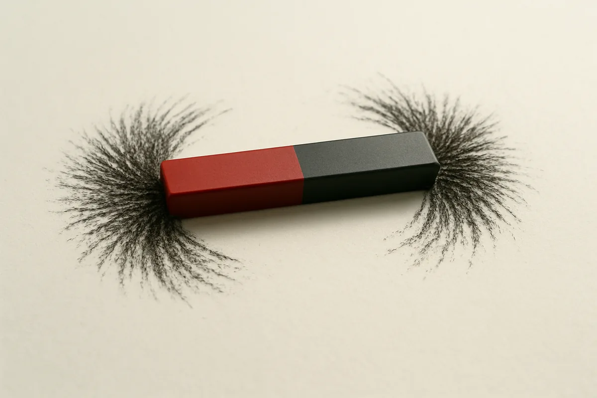
Iron filings can reveal a similar pattern when sprinkled on paper above a bar magnet: each filing becomes temporarily magnetized and turns along the local field. The filings show the pattern’s shape, but their spacing is not a precise measurement of field strength.
Materials and Magnetization
A bar magnet’s behavior depends on both its material and the direction in which it is magnetized. Permanent-magnet materials differ in how strongly they retain magnetization, how much magnetic force they can produce, and how they respond to heat or corrosion. The magnetization direction determines where the poles lie on a particular bar. These differences matter when matching a magnet to a design or interpreting its orientation.
Common Magnetic Materials
Permanent bar magnets are made from several material families, not one universal recipe. Their composition affects field strength, durability, temperature tolerance, and cost.
- Ferrite: This ceramic material is based on iron oxide combined with barium or strontium compounds; it resists corrosion and suits economical, general-purpose magnets.
- Alnico: Made mainly from aluminum, nickel, cobalt, and iron, it retains magnetism well at elevated temperatures but is relatively easy to demagnetize.
- Neodymium-iron-boron: Often called NdFeB, this rare-earth alloy produces a strong field for its size; coatings help protect it from corrosion.
- Samarium-cobalt: This rare-earth alloy combines strong magnetic performance with good resistance to heat and corrosion, making it useful in demanding environments.
Ferrite is often chosen when low cost and corrosion resistance matter more than compact size. Alnico can suit equipment exposed to heat, while NdFeB is selected when high magnetic force from a small magnet is important. Samarium-cobalt may be preferred where both temperature stability and corrosion resistance are priorities. Exact performance varies by grade, dimensions, and operating conditions, so material names alone do not specify a magnet’s strength.
Magnetization and Orientation
In an unmagnetized piece of ferromagnetic material, microscopic regions called magnetic domains point in different directions, so their effects largely cancel. During magnetization, a strong external field shifts domain boundaries and turns more domains toward a common direction. The resulting alignment gives the material a net magnetic moment; coercivity describes how strongly it resists losing that alignment when exposed to an opposing field. A bar magnet can be magnetized axially, with its magnetization running along the long axis, or transversely, across the bar’s width. Axial magnetization places the poles at the two ends. Transverse magnetization places them on opposing long side faces instead. The bar’s shape alone does not identify its pole orientation; the magnetization direction does. Material affects how much magnetization can be retained and how the magnet responds to heat or an opposing field. The chosen direction also determines how the magnet must be positioned in an assembly: an axial bar aligns end-to-end with another component, while a transverse bar presents its poles from the sides. Product drawings and pole markings can specify this orientation, especially when a bar is installed out of sight. A magnet’s grade, dimensions, and direction of magnetization together determine its practical performance; two bars of equal size can behave differently if their materials or magnetization differ.
Common Uses and Demonstrations
A bar magnet is useful for classroom demonstrations because its effects can be observed with simple equipment and familiar objects. Bar magnet experiments can show how a compass responds and which nearby objects are strongly attracted. The same magnet can also hold light items against a suitable steel surface. These demonstrations are different from designing a dependable holder, where the magnet, surface, gap, and load must all be specified.
Demonstrations and Detection
For a classroom magnetic field pattern with iron filings, place a sheet of paper over the magnet and scatter a thin layer of filings across it. The arrangement makes the pattern visible without requiring students to handle the filings directly.
A compass adds directional information: its needle turns to align with the local magnetic field. Use several positions around the magnet to compare readings rather than relying on a single compass placement.
- Cover the magnet with paper or thin card, sprinkle iron filings lightly, and tap the sheet gently to reveal the pattern around the magnet.
- Place a small compass near one end of the magnet, note the needle direction, then repeat at several positions around the magnet.
- Move the compass along a chosen path in small steps and mark the needle direction at each stop to map how the field changes.
- Test a steel paper clip, iron nail, and steel washer separately; attraction indicates a response, but does not measure how much force each needs.
- Compare tested iron or steel objects with aluminum, copper, and wood; an ordinary pull test will not reveal every material with magnetic behavior.
- Place a small steel object at increasing distances from the magnet and record where attraction is no longer detectable with the same setup.
These activities demonstrate observable effects, not a complete material identification method. A simple attraction test is most useful for finding strongly ferromagnetic materials such as iron and many steels; weak magnetic responses may be too small to notice.
Keep the setup consistent when comparing results: use the same magnet, object, orientation, and separation each time. A compass can also be disturbed by nearby magnets or steel objects, so readings should be checked away from other magnetic sources.
Simple Holding Applications
A bar magnet can hold a light paper note against a steel board or keep a small steel label temporarily in place on a flat metal surface. These uses depend on a nearby ferromagnetic surface; a magnet will not hold the same item against wood, glass, or plastic.
For a casual holding task, direct contact with a clean, flat steel surface usually gives a more dependable hold than placing paper, paint, or another layer between the magnet and the steel. The magnet may also slide more easily under a sideways load than it pulls straight away from the surface, so orientation and the direction of the load matter.
An engineered holding application needs defined specifications rather than a general claim that a bar magnet is strong. Identify the magnet material and dimensions, pole orientation, mating surface material and thickness, contact condition, air gap, and required load. Include whether the load pulls directly away or acts in shear, and account for coatings, uneven surfaces, vibration, and any intervening layer. Those details determine whether the magnet can meet the intended holding requirement; a demonstration on a smooth steel board is not a substitute for that evaluation.
Bar Magnets Compared with Other Shapes
A magnet’s outline affects how it fits into a device, how it can be secured, and where its poles can be placed. Bars, discs, rings, and blocks offer different combinations of footprint, thickness, and mounting access. The shape alone does not determine pole placement; the direction of magnetization does. Comparing these practical constraints helps narrow the options before choosing a form for a specific task.
Shape and Design Trade-Offs
Each form suits a different mechanical layout. The comparison below describes common configurations rather than fixed rules: a magnet can be magnetized in more than one direction, so pole locations may differ from the usual arrangement.
| Shape | Mounting | Common pole placement | Space requirements |
|---|---|---|---|
| Bar | Can be held by a clip or clamp along a side, or bonded to a flat support; its long axis provides a clear mounting direction. | With magnetization along its length, the two end faces form opposite poles. | A long, narrow footprint uses little width but needs room along the length, including access near both ends. |
| Disc | Fits a circular recess or can be bonded by one flat face; a shallow pocket can keep it flush with a surface. | Axial magnetization places opposite poles on the two circular faces; diametric magnetization places them on opposite sides of the rim. | Its diameter sets the footprint, while its thickness sets the depth; a thin disc suits a shallow space. |
| Ring | A central bore allows placement around a shaft or fastener, while the flat annular face can seat against a support. | Axial magnetization puts opposite poles on the two flat faces. Radial magnetization places them at the inner and outer cylindrical surfaces. | Allow for the outside diameter, bore, and thickness; the opening reduces the usable magnetic material and provides clearance for hardware. |
| Block | Broad flat faces are convenient for bonding, clamping, or seating in a rectangular pocket. | Poles commonly occupy opposing broad faces, but magnetization across an edge can put them on narrower faces instead. | Its rectangular footprint packs against flat parts; height and width must fit the available pocket or mounting surface. |
These arrangements are typical, not inherent to the outline: pole placement depends on magnetization direction. Ring magnets, in particular, may be magnetized axially or radially, so check the specified orientation before designing a holder or mating part.
A bar-shaped magnet is useful when a long, narrow footprint and end-to-end pole arrangement fit the assembly. A disc reduces length but takes circular face area, while a ring adds a bore for a shaft or fastener. Blocks make efficient contact with flat rectangular supports, though their broad footprint may not fit a narrow channel. Compare the actual mounting surfaces and clearances, not just the magnet’s silhouette.
Choosing a Shape for the Application
Start with the space available: measure the mounting depth, footprint, and clearance around moving parts. A disc may suit a shallow circular recess, a ring can fit around a shaft, and a block can seat against a rectangular face; a bar fits a longer, narrower channel. These are layout matches, not guarantees of a particular magnetic performance.
Next, identify how the magnet will be held in place. A central bore can simplify fastening a ring, while a flat face may make a block or disc easier to bond. Specify the required pole orientation as well: the intended mating surface may call for poles on end faces, broad faces, or the inner and outer surfaces of a ring. Finally, match the form to the task and its mechanical constraints; the suitable shape depends on the application.