
What Neodymium Magnets Are
Neodymium magnets are permanent magnets made from a specific alloy, not from elemental neodymium alone. They are commonly called NdFeB magnets, after their three principal elements: neodymium, iron, and boron. Their material structure gives them lasting magnetism after magnetization. The alloy distinguishes these magnets from other rare earth permanent magnets and from magnets made of a single metal.
Material and Composition
Neodymium magnets are permanent NdFeB magnets made from a neodymium-iron-boron alloy. The name describes the alloy’s principal elements; it does not mean the magnet is a piece of pure neodymium. Elemental neodymium does not retain the same room-temperature permanent-magnet behavior as the engineered alloy, whose crystal structure supports stable magnetization.
The main magnetic phase has the chemical formula Nd2Fe14B: two neodymium atoms, 14 iron atoms, and one boron atom in a repeating crystal structure. Iron supplies much of the material’s ferromagnetic character. Neodymium contributes strong magnetocrystalline anisotropy, which favors magnetization along particular directions in the crystal. Boron helps stabilize the crystal structure that allows these properties to work together.
Commercial neodymium magnet materials are not always a chemically pure, single-phase mixture with exactly that ratio throughout. The Nd2Fe14B phase is the central magnetic component, while grain boundaries and minor phases also occur in the finished material. Manufacturers may add small amounts of other elements, such as dysprosium, terbium, cobalt, aluminum, copper, or niobium, to adjust particular material characteristics or manufacturing behavior. These additions do not change the basic meaning of NdFeB: neodymium, iron, and boron remain the defining constituents.
When the alloy is magnetized, its microscopic magnetic regions become aligned, and the material can retain that alignment as a permanent magnet. The resulting properties come from the combined chemistry and crystal structure, not from neodymium acting alone. That distinction is why the term “neodymium magnet” refers to an engineered alloy rather than to the pure rare-earth element.
How Their Magnetic Strength Is Described
A magnet’s grade and its measured holding force describe different aspects of performance. Grade designations summarize intrinsic magnetic characteristics, while a pull-force result records an outcome under a particular test setup. Contact, the steel target, any gap, and the direction of loading can all change that result. Reading both measures in context gives a more useful basis for comparing magnets than treating either as a universal strength rating.
Magnet grade
A neodymium magnet grade is a material classification, not a guaranteed holding force. The letter N is commonly used for neodymium-iron-boron magnets, followed by a number associated with the material’s maximum magnetic energy product, often written as (BH)max. This energy product describes the peak combination of magnetic flux density and field strength on the material’s demagnetization curve. A higher number generally indicates a greater potential energy product, but it does not by itself tell you how much force a finished magnet will exert on a particular object.
For example, N35 and N52 are familiar grade designations, but the grade alone does not establish the dimensions, pole arrangement, surface contact, or pull force of a finished part. Those factors influence the field and force available in an actual assembly. Grade comparisons are most meaningful when the magnets have comparable geometry and are tested under the same conditions.
Letters or other suffixes may be added to identify properties beyond the base grade, such as a temperature class or a coercivity-related variant. Their meaning and format can differ among manufacturers and grading conventions, so a suffix should be checked against the supplier’s specification rather than interpreted as a universal code. A datasheet can also distinguish a material grade from the properties of the completed magnet. In practice, use grade to compare magnetic material potential, then consult product data for the finished component and its intended operating conditions.
Pull force and working conditions
A stated pull force is the result of a test, not a fixed value that applies to every installation. Manufacturers commonly measure straight separation from a flat steel target under controlled contact conditions. The result can change when the target is smaller or thinner, when paint or another layer creates an air gap, or when the magnet is loaded sideways rather than pulled directly away from the steel.
The comparisons below illustrate how test geometry changes, without assigning a force value to any one setup.
| Test factor | Comparison | Typical effect on the result |
|---|---|---|
| Air gap | 0 mm gap versus a 1 mm spacer | Direct contact usually produces greater attraction; a gap weakens the magnetic coupling. |
| Contact area | Full magnet face on steel versus only half the face contacting | Reduced contact area generally lowers the force available at the interface. |
| Steel thickness | A 1 mm sheet versus a 10 mm plate | A thin target may not provide the same magnetic return path as a thicker plate; the difference depends on magnet and target geometry. |
| Loading direction | Pull perpendicular to the steel versus load parallel to its surface | Straight pull measures separation force, while sideways loading depends more on friction and can cause sliding earlier. |
These are comparisons of test conditions, not universal conversion factors: the actual result depends on the magnet, target steel, and setup. For a real mount, compare data measured with a similar contact surface and loading direction, and account for coatings, gaps, and the stiffness of the steel support. A catalog pull-force figure is most useful as a controlled-test reference; mounting performance can be lower when the installed conditions differ.
Shapes and Magnetization
Neodymium magnets are supplied in geometries that suit different contact surfaces, clearances, and mounting methods. A disc, ring, cylinder, or block describes the magnet’s external form, not its complete magnetic behavior. Magnetization direction determines where the poles sit in relation to that form. The geometry and pole layout must both match the part the magnet will attract, hold, rotate, or sense.
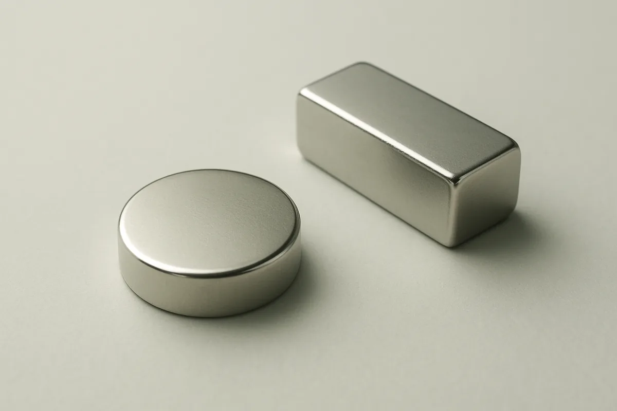
Common Magnet Shapes
Shape affects how a magnet fits against a surface and how it can be retained; it does not, by itself, establish magnetic performance. The table compares common forms by geometry and practical installation considerations.
| Form | Geometry | Mounting considerations | Typical uses |
|---|---|---|---|
| Disc | Round face, diameter D greater than thickness t | Broad flat face suits surface contact; a shallow recess can locate the disc. | Small closures, sensors, and fixtures where a compact circular contact area fits. |
| Cylinder | Round cross-section, with length L greater than diameter D | Fits a drilled bore or sleeve; the bore controls alignment and limits sideways movement. | Linear actuators, positioning fixtures, and assemblies with a cylindrical pocket. |
| Ring | Annular form defined by outside diameter, inside diameter, and thickness | The center opening can accommodate a shaft or fastener; the surrounding face needs support. | Rotating assemblies, couplings, and equipment built around a central shaft. |
| Block | Rectangular dimensions L × W × T | Flat sides provide several mounting faces; a pocket or clamp can resist sliding. | Industrial fixtures, magnetic latches, and linear assemblies with rectangular spaces. |
A disc offers a face suited to flat contact, while a block can present a long edge or broad face depending on how it is installed. Rings preserve a central opening, and cylinders fit naturally into round bores. For any form, the contact area, surrounding clearance, retention method, and intended direction of load affect whether the geometry is practical. These forms are available in many dimensions, so the mating part and mounting space should guide the selection rather than the shape name alone.
Magnetization Direction and Pole Placement
Magnetization direction describes the axis along which a magnet’s poles are arranged; pole placement depends on the design, not just the external shape. In a common axially magnetized disc or cylinder, one circular end face is north and the opposite end face is south. The flat end faces then provide the intended contact surfaces when the magnet is used to attract a steel plate or meet another magnet. A diametrically magnetized cylinder has north and south poles on opposite sides of its curved surface. This arrangement can suit a rotating shaft or sensing application where the field must change as the cylinder turns. A ring is often magnetized axially, placing opposite poles on its two flat annular faces, but specialized rings can use radial or multipole arrangements. Radial designs place poles around the circumference; multipole designs divide a surface into several alternating north and south regions. Blocks may be magnetized through thickness, length, or width. The selected axis determines which pair of faces carries opposite poles, so a block intended to contact a steel panel through its broad face needs a compatible pole orientation. In assemblies, the pole pattern also affects whether two magnets attract or repel and how a sensor detects rotation. Check the specified magnetization direction and pole map against the mounting faces, shaft axis, and working gap before integrating the magnet; a geometrically correct part can still present its field in the wrong direction.
Coatings and Environmental Limits
A neodymium magnet’s coating affects how well its surface withstands moisture, handling, and contact with surrounding materials. The right choice depends on the exposure conditions and the magnet’s construction, including how completely its surfaces and edges are covered. Temperature also matters: a magnet’s usable limit is determined by its grade and design, not by its coating alone. These factors should be considered together when assessing where a magnet can operate.
Coating Options and Exposure Factors
Neodymium magnets can be brittle, so they are commonly coated both to reduce corrosion and to protect the surface from routine contact. A coating is a surface layer, not a substitute for considering the magnet’s construction or the environment it will encounter.
- Nickel-based coatings: A nickel-copper-nickel stack is a common general-purpose finish, offering a smooth surface for indoor use where exposure to moisture and chemicals is limited.
- Zinc coatings: Zinc plating provides a relatively simple, economical finish for dry or mildly humid settings, but it is less suited to persistent moisture or aggressive chemicals.
- Epoxy coatings: Epoxy forms a thicker barrier than many metallic finishes and can suit humid or mildly corrosive environments, provided the coating remains continuous and intact.
- Polymer coatings: Polymer layers can provide electrical insulation and a nonmetallic surface; their suitability depends on the specific material, coverage, and operating environment.
Coating thickness, edge coverage, and any damage during assembly can affect performance as much as the coating category. A design with a fully covered surface may suit exposure that would be unsuitable for a magnet with vulnerable edges or contact points.
Choose corrosion-resistant magnet coatings according to the actual combination of humidity, occasional splashes, chemical contact, and handling involved. No single finish is best for every application, and the coating must also fit the magnet’s dimensions and mounting design.
Corrosion and Temperature Limits
Corrosion resistance depends on an intact barrier between the neodymium-iron-boron material and its surroundings. Scratches, chips, cracks, or worn areas can expose the underlying material; moisture entering at those points may lead to corrosion and progressive coating separation. Cut edges, drilled surfaces, and locations damaged during assembly deserve particular attention because they may not have the same coverage as the finished faces.
A coating does not make every magnet waterproof. A finish suitable for humid air or occasional splashes may not withstand continuous immersion, salt water, cleaning agents, or repeated wet-and-dry cycles. Water can also reach the magnet through seams, mounting features, or small coating defects. The relevant exposure is therefore the complete assembly and its duration of contact, not simply the coating name.
Temperature limits vary with magnet grade and design, so there is no universal operating temperature that applies to every neodymium magnet. Heat can reduce magnetic performance, and sufficiently high temperatures can cause lasting loss; the threshold depends on the material’s resistance to demagnetization as well as the magnet’s dimensions and magnetic circuit. The coating may have its own temperature and aging limits, which can differ from those of the magnet itself.
Assess the expected operating temperature, time at temperature, thermal cycling, and cooling conditions together. A motor or enclosed assembly, for example, may retain heat differently from an exposed magnet in still air. Confirm that both the magnet specification and coating are suitable for those actual conditions rather than assuming a finish raises the magnet’s temperature rating.
Handling and Choosing an Application
Strong neodymium magnets can move suddenly when attraction overcomes your grip, so handling and mounting affect both safety and reliability. A small gap may close with enough force to pinch skin or chip a magnet against a hard surface. Application choices also depend on shape, operating temperature, surrounding materials, and how the magnet will be retained. Consider these factors together rather than choosing by magnetic pull alone.
Safe Handling and Separation
Strongly attracting magnets can snap together before your fingers clear the gap, causing pinches, bruising, or cuts. Their brittle material can also chip or fracture on impact, sending fragments toward nearby people or surfaces.
- Separate a pair by sliding one magnet sideways off the other, keeping your fingers away from the contact line as the overlap decreases.
- For a tight pair, hold each magnet securely and use a nonmagnetic plastic or wooden wedge to open a small gap gradually.
- Do not pull directly against a strong attraction or strike the magnets; sudden release can send a magnet into your hand or a hard surface.
- Keep magnets apart with rigid spacers during storage and transport, and return each one to its own padded compartment after use.
- Protect glass, polished metal, ceramic, and other brittle or finished surfaces with a soft barrier before bringing a magnet nearby.
- Handle larger pieces with a stable grip and clear workspace; use eye protection where a damaged magnet could chip during separation.
Keep loose magnets away from steel tools and fixtures that could draw them out of your hand. These neodymium magnet safety precautions reduce uncontrolled movement, but the force and risk vary with magnet size and arrangement.
Matching a Magnet to an Application
Start with the task: a sensor target, removable fixture, and rotor magnet impose different demands on retention, geometry, and repeatability. Select material and grade against the required magnetic performance at the actual working gap, not from a grade label alone; the assembled circuit and nearby steel influence the result.
Shape should suit the available space and load path. A ring or arc can fit around a shaft in neodymium magnets for motors, while a block may provide a broad mounting face; edges, holes, and thin sections need support because the material is brittle. Check that the chosen geometry leaves room for assembly and does not create unintended contact with moving parts.
Choose a coating for the surrounding environment and the contact surface, then confirm its compatibility with adhesives, oils, cleaning agents, or process chemicals. Temperature is equally application-specific: compare the expected operating and peak temperatures with the supplier’s rating for that exact material and grade, including the time spent hot. Do not assume that a coating or material suitable for a dry indoor fixture will suit a hot, damp, or chemically exposed machine.
Mounting determines whether the magnet can withstand vibration and repeated loading. Adhesive bonding gives a low-profile fit on a clean, compatible surface, while a mechanical pocket, clamp, or retainer can protect the magnet from impact and peel forces. Avoid relying on adhesive alone where a failure could release a moving component.
For a compact, low-impact assembly, a bonded magnet may simplify installation; for vibration or service access, a supported mechanical mount is usually more dependable. The best choice is the one that meets the operating conditions and retains the magnet without loading its brittle edges.